
Synchronverters or virtual synchronous generators are inverters which mimic synchronous generators to provide “synthetic inertia” for ancillary services in electric power systems.

Figure 1. A simple diagram of Synchronverter operation environment
Background
Standard inverters are very low inertia elements. During transient periods, which are mostly because of faults or sudden changes in load, they follow changes rapidly and may cause a worse condition, but synchronous generators have a notable inertia that can maintain their stability.
Recently by using more and more renewable energies, especially solar cells, more inverters have been used in grids and because of mentioned reason, this could endanger power system reliability.
History
Hydro-Québec began requiring synthetic inertia in 2005 as the first grid operator. To counter frequency drop, the grid operator demands a temporary 6% power boost by combining the power electronics with the rotational inertia of a wind turbine rotor. Similar requirements came into effect in Europe in 2016.
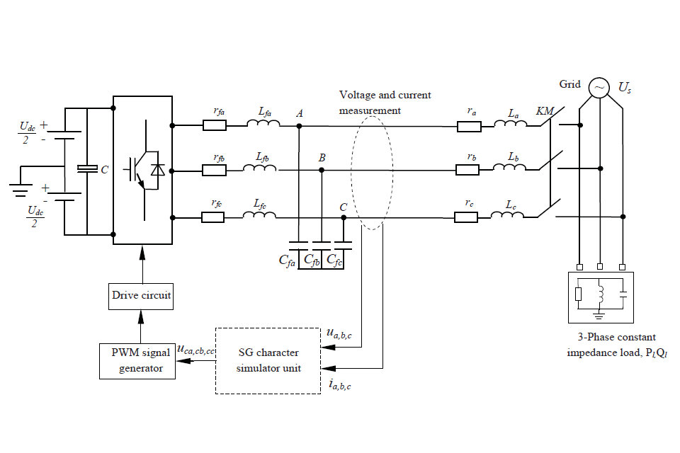
Synchronverter Model
Synchronverter structure can be divided into two parts: power part (see figure 2) and electronic part. The power part is energy transform and transfer path, including the bridge, filter circuit, power line, etc. The electronic part refers to measuring and control units, including sensors and DSP.

Figure 2. Power part of a synchronverter
The important point in modeling synchronverter is to be sure that it has similar dynamic behavior to Synchronous generator (see figure 3). This model is classified into 2-order up to 7-order model, due to its complexity. However, 3-order model is widely used because of proper compromise between accuracy and complexity.

where

Figure 3. The per-phase model of an SG connected to an infinite bus
Control strategy
As shown in the figure 3, when the inverter is controlled as a voltage source, it consists of a synchronization unit to synchronize with the grid and a power loop to regulate the real power and reactive power exchanged with the grid. The synchronization unit often needs to provide frequency and amplitude. But when inverter is controlled as a current source, the synchronization unit is often required to provide the phase of the grid only, so it is much more easier to control it as a current source.
Since a synchronous is inherently able to synchronize with the grid, it is possible to integrate the synchronization function into the power controller without synchronization unit. This results in a compact control unit, as shown in the figure 4.

Figure 4. Typical control structures for a grid-connected power inverter.(a) When controlled as a voltage supply.(b) When controlled as a current supply.

Figure 5. Compact control structure for a grid-connected inverter.
Applications
PV
As mentioned before, synchronverters can be treated like synchronous generator, which make it easier to control the source, so it should be widely used in PV primary energy sources (PES).
HVDC
Wind turbine
DC microgrid
Synchronverter also is suggested to be used in microgrids because DC sources can be coordinated together with the frequency of the ac voltage, without any communication network.

Figure 6. Power part of three-phase synchronverter.
Source from Wikipedia