YUV is a color encoding system typically used as part of a color image pipeline. It encodes a color image or video taking human perception into account, allowing reduced bandwidth for chrominance components, thereby typically enabling transmission errors or compression artifacts to be more efficiently masked by the human perception than using a “direct” RGB-representation. Other color encodings have similar properties, and the main reason to implement or investigate properties of Y′UV would be for interfacing with analog or digital television or photographic equipment that conforms to certain Y′UV standards.
The scope of the terms Y′UV, YUV, YCbCr, YPbPr, etc., is sometimes ambiguous and overlapping. Historically, the terms YUV and Y′UV were used for a specific analog encoding of color information in television systems, while YCbCr was used for digital encoding of color information suited for video and still-image compression and transmission such as MPEG and JPEG. Today, the term YUV is commonly used in the computer industry to describe file-formats that are encoded using YCbCr.
The Y′UV model defines a color space in terms of one luma (Y′) and two chrominance (UV) components. The Y′UV color model is used in the PAL composite color video (excluding PAL-N) standard. Previous black-and-white systems used only luma (Y′) information. Color information (U and V) was added separately via a sub-carrier so that a black-and-white receiver would still be able to receive and display a color picture transmission in the receiver’s native black-and-white format.
Y′ stands for the luma component (the brightness) and U and V are the chrominance (color) components; luminance is denoted by Y and luma by Y′ – the prime symbols (‘) denote gamma compression, with “luminance” meaning physical linear-space brightness, while “luma” is (nonlinear) perceptual brightness.
The YPbPr color model used in analog component video and its digital version YCbCr used in digital video are more or less derived from it, and are sometimes called Y′UV. (CB/PB and CR/PR are deviations from grey on blue–yellow and red–cyan axes, whereas U and V are blue–luminance and red–luminance differences respectively.) The Y′IQ color space used in the analog NTSC television broadcasting system is related to it, although in a more complex way. The YDbDr color space used in the analog SECAM and PAL-N television broadcasting systems, are also related.
As for etymology, Y, Y′, U, and V are not abbreviations. The use of the letter Y for luminance can be traced back to the choice of XYZ primaries. This lends itself naturally to the usage of the same letter in luma (Y′), which approximates a perceptually uniform correlate of luminance. Likewise, U and V were chosen to differentiate the U and V axes from those in other spaces, such as the x and y chromaticity space. See the equations below or compare the historical development of the math.
History
Y′UV was invented when engineers wanted color television in a black-and-white infrastructure. They needed a signal transmission method that was compatible with black-and-white (B&W) TV while being able to add color. The luma component already existed as the black and white signal; they added the UV signal to this as a solution.
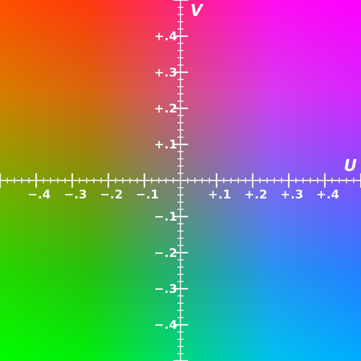
The UV representation of chrominance was chosen over straight R and B signals because U and V are color difference signals. In other words, the U and V signals tell the television to shift the color of a certain pixel without altering its brightness. Or the U and V signals tell the monitor to make one color brighter at the cost of the other and by how much it should be shifted. The higher (or the lower when negative) the U and V values are, the more saturated (colorful) the pixel gets. The closer the U and V values get to zero, the lesser it shifts the color meaning that the red, green and blue lights will be more equally bright, producing a greyer pixel. This is the benefit of using color difference signals, i.e. instead of telling how much red there is to a color, it tells by how much it is more red than green or blue. In turn this meant that when the U and V signals would be zero or absent, it would just display a greyscale image. If R and B were to have been used, these would have non-zero values even in a B&W scene, requiring all three data-carrying signals. This was important in the early days of color television, because old black and white TV signals had no U and V signals present, meaning the color TV would just display it as B&W TV out of the box. In addition, black and white receivers could take the Y′ signal and ignore the U- and V-color signals, making Y′UV backward-compatible with all existing black-and-white equipment, input and output. If the color-TV standard wouldn’t have used color difference signals, it could mean a color TV would make funny colors out of a B&W broadcast or it would need additional circuitry to translate the B&W signal to color. It was necessary to assign a narrower bandwidth to the chrominance channel because there was no additional bandwidth available. If some of the luminance information arrived via the chrominance channel (as it would have if RB signals were used instead of differential UV signals), B&W resolution would have been compromised.
Conversion to/from RGB
SDTV with BT.601
Y′UV signals are typically created from RGB (red, green and blue) source. Weighted values of R, G, and B are summed to produce Y′, a measure of overall brightness or luminance. U and V are computed as scaled differences between Y′ and the B and R values.
BT.601 defines the following constants:
Y′UV is computed from RGB as follows:

The resulting ranges of Y′, U, and V respectively are [0, 1], [−Umax, Umax], and [−Vmax, Vmax].

Inverting the above transformation converts Y′UV to RGB:
Equivalently, substituting values for the constants and expressing them as matrices gives these formulas for BT.601:

HDTV with BT.709

For HDTV the ATSC decided to change the basic values for WR and WB compared to the previously selected values in the SDTV system. For HDTV these values are provided by Rec. 709. This decision further impacted on the matrix for the Y′UV↔RGB conversion so that its member values are also slightly different. As a result, with SDTV and HDTV there are generally two distinct Y′UV representations possible for any RGB triple: a SDTV-Y′UV and a HDTV-Y′UV one. This means in detail that when directly converting between SDTV and HDTV, the luma (Y′) information is roughly the same but the representation of the chroma (U & V) channel information needs conversion. Still in coverage of the CIE 1931 color space the Rec. 709 color space is almost identical to Rec. 601 and covers 35.9%. In contrast to this UHDTV with Rec. 2020 covers a much larger area and would further see its very own matrix set for YUV/Y′UV.
BT.709 defines these weight values:
The conversion matrices & formulas for BT.709 are these:

Notes
The weights used to compute Y′ (top row of matrix) are identical to those used in the Y′IQ color space.
Equal values of red, green and blue (i.e. levels of gray) yield 0 for U and V. Black, RGB=(0, 0, 0), yields YUV=(0, 0, 0). White, RGB=(1, 1, 1), yields YUV=(1, 0, 0).
These formulas are traditionally used in analog televisions and equipment; digital equipment such as HDTV and digital video cameras use Y′CbCr.

Numerical approximations
Prior to the development of fast SIMD floating-point processors, most digital implementations of RGB → Y′UV used integer math, in particular fixed-point approximations. Approximation means that the precision of the used numbers (input data, output data and constant values) is limited, and thus a precision loss of typically about the last binary digit is accepted by whoever makes use of that option in typically a trade-off to improved computation speeds.
In the following examples, the operator ” ” denotes a right shift of a by b binary positions. For clarification the variables are using two suffix characters: “u” is used for the unsigned final representation, and “t” is used for the scaled-down intermediate value. The examples below are given for BT.601 only. The same principle can be used for doing functionally equivalent operations using values that do an acceptable match for data that follows the BT.709 or any other comparable standard.
 ” denotes a right shift of a by b binary positions. For clarification the variables are using two suffix characters: “u” is used for the unsigned final representation, and “t” is used for the scaled-down intermediate value. The examples below are given for BT.601 only. The same principle can be used for doing functionally equivalent operations using values that do an acceptable match for data that follows the BT.709 or any other comparable standard.
Y′ values are conventionally shifted and scaled to the range [16, 235] (referred to as studio swing or “TV levels”) rather than using the full range of [0, 255] (referred to as full swing or “PC levels”). This practice was standardized in SMPTE-125M in order to accommodate signal overshoots (“ringing”) due to filtering. The value 235 accommodates a maximal black-to-white overshoot of 255 − 235 = 20, or 20 / (235 − 16) = 9.1%, which is slightly larger than the theoretical maximal overshoot (Gibbs phenomenon) of about 8.9% of the maximal step. The toe-room is smaller, allowing only 16 / 219 = 7.3% overshoot, which is less than the theoretical maximal overshoot of 8.9%. This is why 16 is added to Y′ and why the Y′ coefficients in the basic transform sum to 220 instead of 255. U and V values, which may be positive or negative, are summed with 128 to make them always positive, giving a studio range of 16–240 for U and V. (These ranges are important in video editing and production, since using the wrong range will result either in an image with “clipped” blacks and whites, or a low-contrast image.)
Studio swing for BT.601
For getting the traditional “studio-swing” 8-bit representation of Y′UV for SDTV/BT.601 the following operations can be used:
1. Basic transform from 8-bit RGB to 16-bit values (Y′: unsigned, U/V: signed, matrix values got rounded so that the later on desired Y′ range of [16..235] and U/V range of [16..240] is reached):
2. Scale down (“>>8”) to 8 bits with rounding (“+128”) (Y′: unsigned, U/V: signed):

3. Add an offset to the values to eliminate any negative values (all results are 8-bit unsigned):

Full swing for BT.601
For getting a “full-swing” 8-bit representation of Y′UV for SDTV/BT.601 the following operations can be used:

1. Basic transform from 8-bit RGB to 16-bit values (Y′: unsigned, U/V: signed, matrix values got rounded so that the later on desired Y′UV range of each [0..255] is reached whilst no overflow can happen):
2. Scale down (“>>8”) to 8-bit values with rounding (“+128”) (Y′: unsigned, U/V: signed):

3. Add an offset to the values to eliminate any negative values (all results are 8-bit unsigned):
Luminance/chrominance systems in general

The primary advantage of luma/chroma systems such as Y′UV, and its relatives Y′IQ and YDbDr, is that they remain compatible with black and white analog television (largely due to the work of Georges Valensi). The Y′ channel saves all the data recorded by black and white cameras, so it produces a signal suitable for reception on old monochrome displays. In this case, the U and V are simply discarded. If displaying color, all three channels are used, and the original RGB information can be decoded.
Another advantage of Y′UV is that some of the information can be discarded in order to reduce bandwidth. The human eye has fairly little spatial sensitivity to color: the accuracy of the brightness information of the luminance channel has far more impact on the image detail discerned than that of the other two. Understanding this human shortcoming, standards such as NTSC and PAL reduce the bandwidth of the chrominance channels considerably. (Bandwidth is in the temporal domain, but this translates into the spatial domain as the image is scanned out.)
Therefore, the resulting U and V signals can be substantially “compressed”. In the NTSC (Y′IQ) and PAL systems, the chrominance signals had significantly narrower bandwidth than that for the luminance. Early versions of NTSC rapidly alternated between particular colors in identical image areas to make them appear adding up to each other to the human eye, while all modern analogue and even most digital video standards use chroma subsampling by recording a picture’s color information at reduced resolution. Only half the horizontal resolution compared to the brightness information is kept (termed 4:2:2 chroma subsampling), and often the vertical resolution is also halved (giving 4:2:0). The 4:x:x standard was adopted due to the very earliest color NTSC standard which used a chroma subsampling of 4:1:1 (where the horizontal color resolution is quartered while the vertical is full resolution) so that the picture carried only a quarter as much color resolution compared to brightness resolution. Today, only high-end equipment processing uncompressed signals uses a chroma subsampling of 4:4:4 with identical resolution for both brightness and color information.
The I and Q axes were chosen according to bandwidth needed by human vision, one axis being that requiring the most bandwidth, and the other (fortuitously at 90 degrees) the minimum. However, true I and Q demodulation was relatively more complex, requiring two analog delay lines, and NTSC receivers rarely used it.
However, this color space conversion is lossy, particularly obvious in crosstalk from the luma to the chroma-carrying wire, and vice versa, in analogue equipment (including RCA connectors to transfer a digital signal, as all they carry is analogue composite video, which is either YUV, YIQ, or even CVBS). Furthermore, NTSC and PAL encoded color signals in a manner that causes high bandwidth chroma and luma signals to mix with each other in a bid to maintain backward compatibility with black and white television equipment, which results in dot crawl and cross color artifacts. When the NTSC standard was created in the 1950s, this was not a real concern since the quality of the image was limited by the monitor equipment, not the limited-bandwidth signal being received. However today′s modern television is capable of displaying more information than is contained in these lossy signals. To keep pace with the abilities of new display technologies, attempts were made since the late 1970s to preserve more of the Y′UV signal while transferring images, such as SCART (1977) and S-Video (1987) connectors.
Instead of Y′UV, Y′CbCr was used as the standard format for (digital) common video compression algorithms such as MPEG-2. Digital television and DVDs preserve their compressed video streams in the MPEG-2 format, which uses a full Y′CbCr color space, although retaining the established process of chroma subsampling. The professional CCIR 601 digital video format also uses Y′CbCr at the common chroma subsampling rate of 4:2:2, primarily for compatibility with previous analog video standards. This stream can be easily mixed into any output format needed.
Y′UV is not an absolute color space. It is a way of encoding RGB information, and the actual color displayed depends on the actual RGB colorants used to display the signal. Therefore, a value expressed as Y′UV is only predictable if standard RGB colorants are used (i.e. a fixed set of primary chromaticities, or particular set of red, green, and blue).
Furthermore, the range of colors and brightnesses (known as the color gamut) of RGB (whether it be BT.601 or Rec.709) is far smaller than the range of colors and brightnesses allowed by Y′UV. This can be very important when converting from Y′UV (or Y′CbCr) to RGB, since the formulas above can produce “invalid” RGB values – i.e., values below 0% or very far above 100% of the range (e.g., outside the standard 16–235 luma range (and 16–240 chroma range) for TVs and HD content, or outside 0–255 for standard definition on PCs). Unless these values are dealt with they will usually be “clipped” (i.e., limited) to the valid range of the channel affected. This changes the hue of the color, which is very undesirable, so it is therefore often considered better to desaturate the offending colors such that they fall within the RGB gamut. Likewise, when RGB at a given bit depth is converted to YUV at the same bit depth, several RGB colors can become the same Y′UV color, resulting in information loss.
Relation with Y′CbCr
Y′UV is often used as a term for YCbCr. However, they are completely different formats with different scale factors.
Nevertheless, the relationship between them in the standard case is simple. In particular, the Y channel is the same in both, both Cb and U are proportional to (B-Y), and both Cr and V are proportional to (R-Y).
Source From Wikipedia