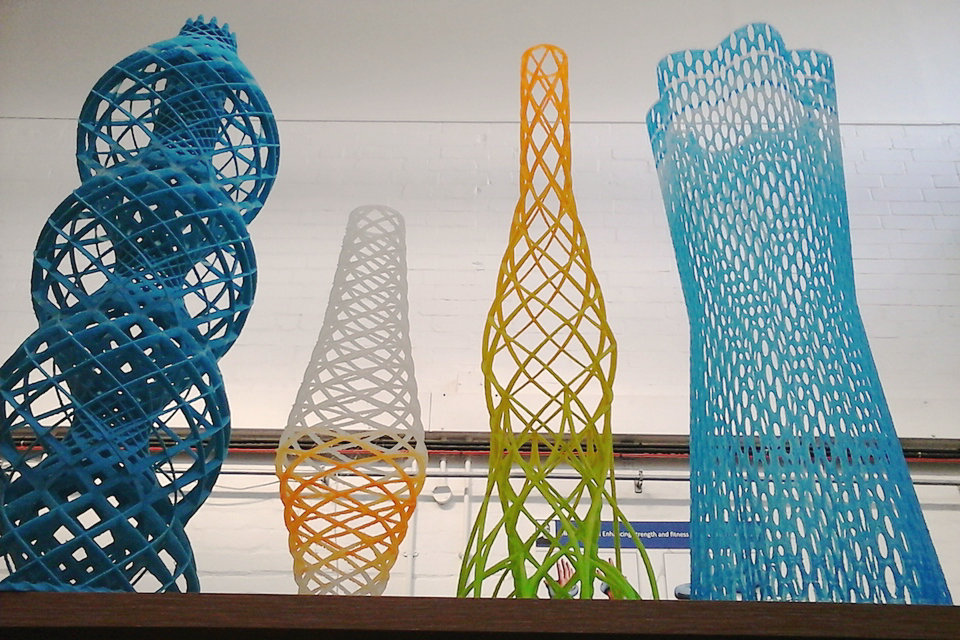
Rapid prototyping is a group of techniques used to quickly fabricate a scale model of a physical part or assembly using three-dimensional computer aided design (CAD) data. Construction of the part or assembly is usually done using 3D printing or “additive layer manufacturing” technology.
The first methods for rapid prototyping became available in the late 1980s and were used to produce models and prototype parts. Today, they are used for a wide range of applications and are used to manufacture production-quality parts in relatively small numbers if desired without the typical unfavorable short-run economics. This economy has encouraged online service bureaus. Historical surveys of RP technology start with discussions of simulacra production techniques used by 19th-century sculptors. Some modern sculptors use the progeny technology to produce exhibitions. The ability to reproduce designs from a dataset has given rise to issues of rights, as it is now possible to interpolate volumetric data from one-dimensional images.
As with CNC subtractive methods, the computer-aided-design – computer-aided manufacturing CAD -CAM workflow in the traditional Rapid Prototyping process starts with the creation of geometric data, either as a 3D solid using a CAD workstation, or 2D slices using a scanning device. For Rapid prototyping this data must represent a valid geometric model; namely, one whose boundary surfaces enclose a finite volume, contain no holes exposing the interior, and do not fold back on themselves. In other words, the object must have an “inside”. The model is valid if for each point in 3D space the computer can determine uniquely whether that point lies inside, on, or outside the boundary surface of the model. CAD post-processors will approximate the application vendors’ internal CAD geometric forms (e.g., B-splines) with a simplified mathematical form, which in turn is expressed in a specified data format which is a common feature in additive manufacturing: STL (stereolithography) a de facto standard for transferring solid geometric models to SFF machines. To obtain the necessary motion control trajectories to drive the actual SFF, rapid prototyping, 3D printing or additive manufacturing mechanism, the prepared geometric model is typically sliced into layers, and the slices are scanned into lines (producing a “2D drawing” used to generate trajectory as in CNC’s toolpath), mimicking in reverse the layer-to-layer physical building process.
Overview:
The rapid prototyping is a process used to make plastic articles, metal or ceramic. Also known by its English name as “additive technology”, since its manufacturing process is to add material layer by layer. In some cases with physical properties that are similar to what would be produced by conventional methods, such as injection molding and extrusion, or blow molding, this way you avoid making the expensive molds to make a prototype that could change its shape. Initially rapid prototypingit was only used for the manufacture of prototypes. Nowadays it is used as a manufacturing process more. An example is found in the dental sector, where it is used to make metal structures that will later be covered with ceramic, creating dental crowns and bridges.
Design prototypes:
They serve to evaluate aesthetic and ergonomic aspects.
Geometric prototypes:
They are used to test geometric agreement, form and assemblies.
Functional prototypes:
They show the characteristics and behavior patterns in a test of the final product.
Technical prototypes:
They are used to evaluate all the functions of the final piece.
The concept
Rapid prototyping integrates three essential concepts: time, cost and complexity of shapes.
Time: the goal of rapid prototyping is to quickly produce models, with the aim of reducing product development time.
Cost: Rapid prototyping allows prototypes to be made without the need for costly tooling, while guaranteeing the performance of the final product. We are therefore able to explore different variants of the product being developed in order to retain the most appropriate solution.
Complexity of forms: modern numerical control machines (CNC milling, 3D printers,…) are capable of producing extremely complex shapes (inclusion, cavity…), which can not be realized by processes such as machining for example.
Application areas
3D production systems allow electric cars to be built and tested in one year. Rapid prototyping is also commonly applied in software engineering to try out new business models and application architectures.
History
In the 1970s, Joseph Henry Condon and others at Bell Labs developed the Unix Circuit Design System (UCDS), automating the laborious and error-prone task of manually converting drawings to fabricate circuit boards for the purposes of research and development.
By the 1980s, U.S. policy makers and industrial managers were forced to take note that America’s dominance in the field of machine tool manufacturing evaporated, in what was named the machine tool crisis. Numerous projects sought to counter these trends in the traditional CNC CAM area, which had begun in the US. Later when Rapid Prototyping Systems moved out of labs to be commercialized, it was recognized that developments were already international and U.S. rapid prototyping companies would not have the luxury of letting a lead slip away. The National Science Foundation was an umbrella for the National Aeronautics and Space Administration (NASA), the US Department of Energy, the US Department of Commerce NIST, the US Department of Defense, Defense Advanced Research Projects Agency (DARPA), and the Office of Naval Research coordinated studies to inform strategic planners in their deliberations. One such report was the 1997 Rapid Prototyping in Europe and Japan Panel Report in which Joseph J. Beaman founder of DTM Corporation provides a historical perspective:
“The roots of rapid prototyping technology can be traced to practices in topography and photosculpture. Within TOPOGRAPHY Blanther (1892) suggested a layered method for making a mold for raised relief paper topographical maps.The process involved cutting the contour lines on a series of plates which were then stacked. Matsubara (1974) of Mitsubishi proposed a topographical process with a photo-hardening photopolymer resin to form thin layers stacked to make a casting mold. PHOTOSCULPTURE was a 19th-century technique to create exact three-dimensional replicas of objects. Most famously Francois Willeme (1860) placed 24 cameras in a circular array and simultaneously photographed an object. The silhouette of each photograph was then used to carve a replica. Morioka (1935, 1944) developed a hybrid photo sculpture and topographic process using structured light to photographically create contour lines of an object.The lines could then be developed into sheets and cut and stacked, or projected onto stock material for carving. The Munz(1956) Process reproduced a three-dimensional image of an object by selectively exposing, layer by layer, a photo emulsion on a lowering piston. After fixing, a solid transparent cylinder contains an image of the object. ”
— Joseph J. Beaman
The technologies referred to as Solid Freeform Fabrication are what we recognize today as rapid prototyping, 3D printing or additive manufacturing: Swainson (1977), Schwerzel (1984) worked on polymerization of a photosensitive polymer at the intersection of two computer controlled laser beams. Ciraud (1972) considered magnetostatic or electrostatic deposition with electron beam, laser or plasma for sintered surface cladding. These were all proposed but it is unknown if working machines were built. Hideo Kodama of Nagoya Municipal Industrial Research Institute was the first to publish an account of a solid model fabricated using a photopolymer rapid prototyping system (1981). Even at that early date the technology was seen as having a place in manufacturing practice. A low resolution, low strength output had value in design verification, mould making, production jigs and other areas. Outputs have steadily advanced toward higher specification uses.
Innovations are constantly being sought, to improve speed and the ability to cope with mass production applications. A dramatic development which RP shares with related CNC areas is the freeware open-sourcing of high level applications which constitute an entire CAD-CAM toolchain. This has created a community of low res device manufacturers. Hobbyists have even made forays into more demanding laser-effected device designs.
Techniques
Approximately from the beginning of the 1980s, technologies of forming three-dimensional objects began to develop intensively not by removing material (turning, milling, EDM) or changing the shape of the workpiece (forging, stamping, pressing), but by gradually increasing (adding) a material or changing the phase state of a substance in a given region of space. At the moment, significant progress has been made in the technology of layer-by-layer formation of three-dimensional objects based on their computer images. These technologies are known by various terms, for example, SFF (Solid Freeform Fabrication), FFFF (Fast Free Form Fabrication) or CARP (Computer Aided Rapid Prototyping), but the most widely used :
Additive manufacturing
The most accessible “rapid prototyping” technique is additive manufacturing.
She understands:
The stereolithography; in a bath of liquid plastic and polymerizes it using a beam of light (laser, UV, IR…) (we speak of photopolymerization (SLA).
Deposition of molten wire (FDM): mechanical deposition of plastic material in successive layers. The machine deposits a plastic wire through a nozzle. The process is mechanical.
The sand printing: As the fused deposition modeling, it is a mechanical deposition material by successive layer, it allows the manufacture of sand molds (molding) for producing metal pieces (good material)
The Laser Direct Building successive layers: melting metal powders injected coaxially to a laser beam power to achieve metal deposition in successive layers.
The laser sintering, in a fine powder plastic container and the frit (Selective sintering, melting of the grains of this plastic powder, abbreviation SLS).
Case of rapid prototyping by wire deposition – FDM (fused deposition Modeling)
This technique consists of melting a resin (usually a thermoplastic type ABS) through a nozzle heated to high temperature. A molten filament (of the order of a tenth of a millimeter) comes out. This wire is deposited online and is glued by fusion on what has been filed beforehand.
These machines are intended for both rapid prototyping and direct digital production, a developing market. The big interest of the FDM is to allow to create parts in good material, having mechanical characteristics, thermal and stability identical to the injected thermoplastic parts. This technique also has an important advantage concerning the support structure necessary for the production of the parts, since this construction support is in most cases made of a material other than the thermoplastic material which itself is soluble.
The density of the parts is also adjustable because this technique by addition of material allows to fill only partially the volumes by creating a honeycomb network – a gain appreciated for the production times and the lightness of the parts made.
The process has been patented by Stratasys. This patent expired recently (2012), new players have embarked on the manufacture of FDM machines, attempting to seduce mainly individual consumers, with machines such as the “CUBEX” Cubify / 3D System, or the “REPLICATOR” of Makerbot / Stratasys. These machines are usually sold for less than $ 3000.
Techniques for obtaining a prototype that are not additive manufacturing techniques
UTGV or Very High Speed Machining with multi-axis numerical control machines; the disadvantage is the waste of material. You can machine a part or its mold.
Digital milling. This is a subtractive method.
IT resources
They are taking an increasing place in rapid prototyping. Those are:
the reverse engineering (acquisition systems forms associated with surface reconstruction software);
the computer-aided design (CAD), manufacturing methods by adding and removing material;
post-treatments.
Possible geometries with these prototypes
In general you can create almost all kinds of geometries. Even many times geometries can be manufactured that other traditional processes can not manufacture. The fact is that the result of rapid prototypes is what one can create in a CAD or 3rd dimension file. It must be taken into account that the prototype that is created in these programs may not always be produced on a large scale, since in the case of the rapid prototype it is only a sample of the concept that will be created and the next step we can take on the base of that prototype is engineering
Types of Rapid Prototyping
Ballistic particle manufacturing (BPM)
Directed light fabrication (DLF)
Direct-shell production casting (DSPC)
Fused deposition modeling (FDM)
Laminated object manufacturing (LOM)
Laminated resin printing (LRP)
Shape deposition manufacturing (SDM) (and Mold SDM)
Solid ground curing (SGC)
Selective laser sintering (SLS)
Selective laser melting (SLM)
Stereo lithography (SLA)
All of these technologies assume the presence of a three-dimensional computer model of the part. Most well-known CAD systems provide export models in the standard for rapid prototyping format STL.
Some of the BP installations are called 3D printers.
Procedure
Rapid prototyping processes are thus production processes which have the goal of converting existing CAD data directly and quickly into workpieces, if possible without manual detours or forms. The relevant data interface for this process group is the STL format. The known under the term of rapid prototyping since the 1980s methods are usually primary molding, which build the workpiece layers of shapeless or form-neutral material using physical and / or chemical effects.
Among the methods of rapid prototyping include:
| process | materials |
|---|---|
| Contour Crafting (CC) | concrete |
| Electron beam melting (EBM) | metals |
| Fused Deposition Modeling (FDM) | ABS , polylactides |
| Laminated Object Modeling (LOM) | Paper, plastics, ceramics or aluminum |
| Laser Engineered Net Shaping (LENS) | metals |
| Laser Cladding | metals |
| Multi Jet Modeling (MJM) | waxy thermoplastics , UV-sensitive photopolymers , sand, metal powder, glass powder |
| polyamide cast | polyamides |
| Selective laser melting (SLM) | Metals, plastics, ceramics |
| Selective Laser Sintering (SLS) | Thermoplastics : polycarbonates , polyamides , polyvinyl chloride , metals, ceramics |
| Space Puzzle Molding (SPM) | plastics |
| Stereolithography (SL or SLA) | liquid duromers or elastomers |
| Binder Jetting (3D printing) | Powders and granules |
Methods such as FDM, SLM and EBM, which apply the material in layers, are also referred to as 3D printing.
Application
In recent years, the fields of application of rapid prototyping, which initially focused on making models and prototypes, have been extended to other fields. These include:
the use as a tool: Rapid Tooling and
the use as a finished part: Rapid Manufacturing.
Due to the breadth of current applications, it is currently appropriate to speak of the use of generative manufacturing techniques.
In conjunction with other modern technologies such as reverse engineering (digitizing), CAD, virtual reality and modern tooling processes, the process chain within product development is also known as Rapid Product Development.
In addition, there are also terms such as generative manufacturing processes, additive manufacturing, coating manufacturing, Freeform Fabrication, Desktop Manufacturing, Layer Manufacturing Technology, Advanced Digital Manufacturing (ADM), e-Manufacturing, etc.
Due to this meanwhile strongly increased range of use of generatively produced components, new requirements are always placed on generatively manufactured components, which can be solved by following technologies in generative processes such as surface technology. So it is possible by ablative processes such as sandblasting or vibratory finishing to level the levels due to the construction process. It is also possible to paint or metallize the generatively manufactured workpieces.
Special applications
engineering analysis
stream visualization
medicine
Benefits
Reducing the duration of the technical preparation of the production of new products by 2-4 times.
Reducing the cost of production, especially in small-scale or single production by 2-3 times.
Significant increase in production flexibility.
Improving the competitiveness of production.
Through the use of computer technology, integration with CAD systems.
Disadvantages
The relatively high cost of installations and consumables.
Relatively low strength models (depending on the material).
Production time
Over time, the disadvantages are gradually eliminated – the prices are reduced, the choice of technologies and materials increases.
Source from Wikipedia