Principle of Electric motor

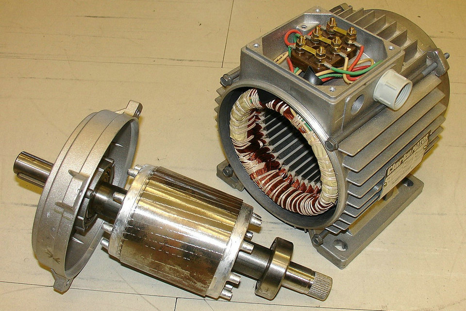
An electric motor is an electromechanical converter (electric machine) that converts electrical power into mechanical power. In conventional electric motors generate current-carrying conductor coils magnetic fields whose mutual attraction and repulsion forces are implemented in motion. Thus, the electric motor is the counterpart to the very similar constructed generator that converts motor power into electrical power. Electric motors usually generate rotating movements, but they can also be used for translatory movementsbe built (linear actuator). Electric motors are used to drive many equipment, machinery and vehicles.
Principle of operation
Electric motors are devices that transform electrical energy into mechanical energy. The means of this transformation of energy in electric motors is the magnetic field. There are different types of electric motors and each type has different components whose structure determines the interaction of the electric and magnetic flows that cause the force or torque of the motor.
The fundamental principle is that describes how a force is caused by the interaction of a point electric charge q in electric and magnetic fields is the Lorentz law :
where:

q : punctual electric charge
E : Electric field
v : particle speed
B : magnetic field density
In the case of a purely electric field the expression of the equation is reduced to:
The force in this case is determined only by the charge q and by the electric field E. It is the Coulomb force that acts along the conductor originating the electrical flow, for example in the coils of the stator of the induction machines or in the rotor of the DC motors.
In the case of a purely magnetic field:
The force is determined by the charge, the magnetic field density B and the speed of the load v. This force is perpendicular to the magnetic field and the direction of the velocity of the load. Normally there are many loads in motion so it is convenient to rewrite the expression in terms of charge density Fv (force per unit volume):
To the product
Then the resulting expression describes the force produced by the interaction of the current with a magnetic field:
This is a basic principle that explains how forces originate in electromechanical systems such as electric motors. However, the complete description for each type of electric motor depends on its components and its construction.
Linear motor
A linear motor is essentially any electric motor that has been “unrolled” so that, instead of producing a torque (rotation), it produces a straight-line force along its length.
Linear motors are most commonly induction motors or stepper motors. Linear motors are commonly found in many roller-coasters where the rapid motion of the motorless railcar is controlled by the rail. They are also used in maglev trains, where the train “flies” over the ground. On a smaller scale, the 1978 era HP 7225A pen plotter used two linear stepper motors to move the pen along the X and Y axes.
Electromagnetism
Force and torque
The fundamental purpose of the vast majority of the world’s electric motors is to electromagnetically induce relative movement in an air gap between a stator and rotor to produce useful torque or linear force.
According to Lorentz force law the force of a winding conductor can be given simply by:
or more generally, to handle conductors with any geometry:
The most general approaches to calculating the forces in motors use tensors.
Power
Where rpm is shaft speed and T is torque, a motor’s mechanical power output Pem is given by,
in British units with T expressed in foot-pounds,
in SI units with shaft angular speed expressed in radians per second, and T expressed in newton-meters,
For a linear motor, with force F expressed in newtons and velocity v expressed in meters per second,
In an asynchronous or induction motor, the relationship between motor speed and air gap power is, neglecting skin effect, given by the following:
Rr – rotor resistance
Ir2 – square of current induced in the rotor
s – motor slip; i.e., difference between synchronous speed and slip speed, which provides the relative movement needed for current induction in the rotor.
Back emf
Since the armature windings of a direct-current or universal motor are moving through a magnetic field, they have a voltage induced in them. This voltage tends to oppose the motor supply voltage and so is called “back electromotive force (emf)”. The voltage is proportional to the running speed of the motor. The back emf of the motor, plus the voltage drop across the winding internal resistance and brushes, must equal the voltage at the brushes. This provides the fundamental mechanism of speed regulation in a DC motor. If the mechanical load increases, the motor slows down; a lower back emf results, and more current is drawn from the supply. This increased current provides the additional torque to balance the new load.
In AC machines, it is sometimes useful to consider a back emf source within the machine; as an example, this is of particular concern for close speed regulation of induction motors on VFDs.
Losses
Motor losses are mainly due to resistive losses in windings, core losses and mechanical losses in bearings, and aerodynamic losses, particularly where cooling fans are present, also occur.
Losses also occur in commutation, mechanical commutators spark, and electronic commutators and also dissipate heat.
Efficiency
To calculate a motor’s efficiency, the mechanical output power is divided by the electrical input power:
where
where
Various regulatory authorities in many countries have introduced and implemented legislation to encourage the manufacture and use of higher-efficiency electric motors.
Goodness factor
Eric Laithwaite proposed a metric to determine the ‘goodness’ of an electric motor:
Where:
From this, he showed that the most efficient motors are likely to have relatively large magnetic poles. However, the equation only directly relates to non PM motors.
Performance parameters
Torque capability of motor types
All the electromagnetic motors, and that includes the types mentioned here derive the torque from the vector product of the interacting fields. For calculating the torque it is necessary to know the fields in the air gap. Once these have been established by mathematical analysis using FEA or other tools the torque may be calculated as the integral of all the vectors of force multiplied by the radius of each vector. The current flowing in the winding is producing the fields and for a motor using a magnetic material the field is not linearly proportional to the current. This makes the calculation difficult but a computer can do the many calculations needed.
Once this is done a figure relating the current to the torque can be used as a useful parameter for motor selection. The maximum torque for a motor will depend on the maximum current although this will usually be only usable until thermal considerations take precedence.
When optimally designed within a given core saturation constraint and for a given active current (i.e., torque current), voltage, pole-pair number, excitation frequency (i.e., synchronous speed), and air-gap flux density, all categories of electric motors or generators will exhibit virtually the same maximum continuous shaft torque (i.e., operating torque) within a given air-gap area with winding slots and back-iron depth, which determines the physical size of electromagnetic core. Some applications require bursts of torque beyond the maximum operating torque, such as short bursts of torque to accelerate an electric vehicle from standstill. Always limited by magnetic core saturation or safe operating temperature rise and voltage, the capacity for torque bursts beyond the maximum operating torque differs significantly between categories of electric motors or generators.
Capacity for bursts of torque should not be confused with field weakening capability. Field weakening allows an electric machine to operate beyond the designed frequency of excitation. Field weakening is done when the maximum speed cannot be reached by increasing the applied voltage. This applies to only motors with current controlled fields and therefore cannot be achieved with permanent magnet motors.
Electric machines without a transformer circuit topology, such as that of WRSMs or PMSMs, cannot realize bursts of torque higher than the maximum designed torque without saturating the magnetic core and rendering any increase in current as useless. Furthermore, the permanent magnet assembly of PMSMs can be irreparably damaged, if bursts of torque exceeding the maximum operating torque rating are attempted.
Electric machines with a transformer circuit topology, such as induction machines, induction doubly-fed electric machines, and induction or synchronous wound-rotor doubly-fed (WRDF) machines, exhibit very high bursts of torque because the emf-induced active current on either side of the transformer oppose each other and thus contribute nothing to the transformer coupled magnetic core flux density, which would otherwise lead to core saturation.
Electric machines that rely on induction or asynchronous principles short-circuit one port of the transformer circuit and as a result, the reactive impedance of the transformer circuit becomes dominant as slip increases, which limits the magnitude of active (i.e., real) current. Still, bursts of torque that are two to three times higher than the maximum design torque are realizable.
The brushless wound-rotor synchronous doubly-fed (BWRSDF) machine is the only electric machine with a truly dual ported transformer circuit topology (i.e., both ports independently excited with no short-circuited port). The dual ported transformer circuit topology is known to be unstable and requires a multiphase slip-ring-brush assembly to propagate limited power to the rotor winding set. If a precision means were available to instantaneously control torque angle and slip for synchronous operation during motoring or generating while simultaneously providing brushless power to the rotor winding set, the active current of the BWRSDF machine would be independent of the reactive impedance of the transformer circuit and bursts of torque significantly higher than the maximum operating torque and far beyond the practical capability of any other type of electric machine would be realizable. Torque bursts greater than eight times operating torque have been calculated.
Continuous torque density
The continuous torque density of conventional electric machines is determined by the size of the air-gap area and the back-iron depth, which are determined by the power rating of the armature winding set, the speed of the machine, and the achievable air-gap flux density before core saturation. Despite the high coercivity of neodymium or samarium-cobalt permanent magnets, continuous torque density is virtually the same amongst electric machines with optimally designed armature winding sets. Continuous torque density relates to method of cooling and permissible period of operation before destruction by overheating of windings or permanent magnet damage.
Other sources state that various e-machine topologies have differing torque density. One source shows the following:
| Electric machine type | Specific torque density (Nm/kg) |
|---|---|
| SPM — brushless ac, 180° current conduction | 1.0 |
| SPM — brushless ac, 120° current conduction | 0.9-1.15 |
| IM, asynchronous machine | 0.7-1.0 |
| IPM, interior permanent magnet machine | 0.6-0.8 |
| VRM, doubly salient reluctance machine | 0.7-1.0 |
where — specific torque density is normalized to 1.0 for the SPM — brushless ac, 180° current conduction, SPM is Surface Permanent Magnet machine.
Torque density is approximately four times greater for electric motors which are liquid cooled, as compared to those which are air cooled.
A source comparing direct current (DC), induction motors (IM), permanent magnet synchronous motors (PMSM) and switched reluctance motors (SRM) showed:
| Characteristic | dc | IM | PMSM | SRM |
|---|---|---|---|---|
| Torque density | 3 | 3.5 | 5 | 4 |
| Power density | 3 | 4 | 5 | 3.5 |
Another source notes that permanent-magnet synchronous machines of up to 1 MW have considerably higher torque density than induction machines.
Continuous power density
The continuous power density is determined by the product of the continuous torque density and the constant torque speed range of the electric machine.
Special magnetic motors
Rotary
Ironless or coreless rotor motor
Nothing in the principle of any of the motors described above requires that the iron (steel) portions of the rotor actually rotate. If the soft magnetic material of the rotor is made in the form of a cylinder, then (except for the effect of hysteresis) torque is exerted only on the windings of the electromagnets. Taking advantage of this fact is the coreless or ironless DC motor, a specialized form of a permanent magnet DC motor. Optimized for rapid acceleration, these motors have a rotor that is constructed without any iron core. The rotor can take the form of a winding-filled cylinder, or a self-supporting structure comprising only the magnet wire and the bonding material. The rotor can fit inside the stator magnets; a magnetically soft stationary cylinder inside the rotor provides a return path for the stator magnetic flux. A second arrangement has the rotor winding basket surrounding the stator magnets. In that design, the rotor fits inside a magnetically soft cylinder that can serve as the housing for the motor, and likewise provides a return path for the flux.
Because the rotor is much lighter in weight (mass) than a conventional rotor formed from copper windings on steel laminations, the rotor can accelerate much more rapidly, often achieving a mechanical time constant under one ms. This is especially true if the windings use aluminum rather than the heavier copper. But because there is no metal mass in the rotor to act as a heat sink, even small coreless motors must often be cooled by forced air. Overheating might be an issue for coreless DC motor designs. Modern software, such as Motor-CAD, can help to increase the thermal efficiency of motors while still in the design stage.
Among these types are the disc-rotor types, described in more detail in the next section.
The vibrating alert of cellular phones is sometimes generated by tiny cylindrical permanent-magnet field types, but there are also disc-shaped types that have a thin multipolar disc field magnet, and an intentionally unbalanced molded-plastic rotor structure with two bonded coreless coils. Metal brushes and a flat commutator switch power to the rotor coils.
Related limited-travel actuators have no core and a bonded coil placed between the poles of high-flux thin permanent magnets. These are the fast head positioners for rigid-disk (“hard disk”) drives. Although the contemporary design differs considerably from that of loudspeakers, it is still loosely (and incorrectly) referred to as a “voice coil” structure, because some earlier rigid-disk-drive heads moved in straight lines, and had a drive structure much like that of a loudspeaker.
Pancake or axial rotor motor
The printed armature or pancake motor has the windings shaped as a disc running between arrays of high-flux magnets. The magnets are arranged in a circle facing the rotor with space in between to form an axial air gap. This design is commonly known as the pancake motor because of its flat profile. The technology has had many brand names since its inception, such as ServoDisc.
The printed armature (originally formed on a printed circuit board) in a printed armature motor is made from punched copper sheets that are laminated together using advanced composites to form a thin rigid disc. The printed armature has a unique construction in the brushed motor world in that it does not have a separate ring commutator. The brushes run directly on the armature surface making the whole design very compact.
An alternative manufacturing method is to use wound copper wire laid flat with a central conventional commutator, in a flower and petal shape. The windings are typically stabilized with electrical epoxy potting systems. These are filled epoxies that have moderate, mixed viscosity and a long gel time. They are highlighted by low shrinkage and low exotherm, and are typically UL 1446 recognized as a potting compound insulated with 180 °C, Class H rating.
The unique advantage of ironless DC motors is the absence of cogging (torque variations caused by changing attraction between the iron and the magnets). Parasitic eddy currents cannot form in the rotor as it is totally ironless, although iron rotors are laminated. This can greatly improve efficiency, but variable-speed controllers must use a higher switching rate (>40 kHz) or DC because of decreased electromagnetic induction.
These motors were originally invented to drive the capstan(s) of magnetic tape drives, where minimal time to reach operating speed and minimal stopping distance were critical. Pancake motors are widely used in high-performance servo-controlled systems, robotic systems, industrial automation and medical devices. Due to the variety of constructions now available, the technology is used in applications from high temperature military to low cost pump and basic servos.
Another approach (Magnax) is to use a single stator sandwiched between two rotors. One such design has produced peak power of 15 kW/kg, sustained power around 7.5 kW/kg. This yokeless axial flux motor offers a shorter flux path, keeping the magnets further from the axis. The design allows has zero winding overhang; 100 percent of the windings are active. This is enhanced with the use of rectangular-section copper wire. The motors can be stacked to work in parallel. Instabilities are minimized by ensuring that the two rotor discs put equal and opposing forces onto the stator disc. The rotors are connected directly to one another via a shaft ring, cancelling out the magnetic forces.
Magnax motors range in size from.15–5.4 metres (5.9 in–17 ft 8.6 in) in diameter.
Servo motor
A servomotor is a motor, very often sold as a complete module, which is used within a position-control or speed-control feedback control system. Servomotors are used in applications such as machine tools, pen plotters, and other process systems. Motors intended for use in a servomechanism must have well-documented characteristics for speed, torque, and power. The speed vs. torque curve is quite important and is high ratio for a servo motor. Dynamic response characteristics such as winding inductance and rotor inertia are also important; these factors limit the overall performance of the servomechanism loop. Large, powerful, but slow-responding servo loops may use conventional AC or DC motors and drive systems with position or speed feedback on the motor. As dynamic response requirements increase, more specialized motor designs such as coreless motors are used. AC motors’ superior power density and acceleration characteristics compared to that of DC motors tends to favor permanent magnet synchronous, BLDC, induction, and SRM drive applications.
A servo system differs from some stepper motor applications in that the position feedback is continuous while the motor is running. A stepper system inherently operates open-loop – relying on the motor not to “miss steps” for short term accuracy – with any feedback such as a “home” switch or position encoder being external to the motor system. For instance, when a typical dot matrix computer printer starts up, its controller makes the print head stepper motor drive to its left-hand limit, where a position sensor defines home position and stops stepping. As long as power is on, a bidirectional counter in the printer’s microprocessor keeps track of print-head position.
Stepper motor
Stepper motors are a type of motor frequently used when precise rotations are required. In a stepper motor an internal rotor containing permanent magnets or a magnetically soft rotor with salient poles is controlled by a set of external magnets that are switched electronically. A stepper motor may also be thought of as a cross between a DC electric motor and a rotary solenoid. As each coil is energized in turn, the rotor aligns itself with the magnetic field produced by the energized field winding. Unlike a synchronous motor, in its application, the stepper motor may not rotate continuously; instead, it “steps”—starts and then quickly stops again—from one position to the next as field windings are energized and de-energized in sequence. Depending on the sequence, the rotor may turn forwards or backwards, and it may change direction, stop, speed up or slow down arbitrarily at any time.
Simple stepper motor drivers entirely energize or entirely de-energize the field windings, leading the rotor to “cog” to a limited number of positions; more sophisticated drivers can proportionally control the power to the field windings, allowing the rotors to position between the cog points and thereby rotate extremely smoothly. This mode of operation is often called microstepping. Computer controlled stepper motors are one of the most versatile forms of positioning systems, particularly when part of a digital servo-controlled system.
Stepper motors can be rotated to a specific angle in discrete steps with ease, and hence stepper motors are used for read/write head positioning in computer floppy diskette drives. They were used for the same purpose in pre-gigabyte era computer disk drives, where the precision and speed they offered was adequate for the correct positioning of the read/write head of a hard disk drive. As drive density increased, the precision and speed limitations of stepper motors made them obsolete for hard drives—the precision limitation made them unusable, and the speed limitation made them uncompetitive—thus newer hard disk drives use voice coil-based head actuator systems. (The term “voice coil” in this connection is historic; it refers to the structure in a typical (cone type) loudspeaker. This structure was used for a while to position the heads. Modern drives have a pivoted coil mount; the coil swings back and forth, something like a blade of a rotating fan. Nevertheless, like a voice coil, modern actuator coil conductors (the magnet wire) move perpendicular to the magnetic lines of force.)
Stepper motors were and still are often used in computer printers, optical scanners, and digital photocopiers to move the optical scanning element, the print head carriage (of dot matrix and inkjet printers), and the platen or feed rollers. Likewise, many computer plotters (which since the early 1990s have been replaced with large-format inkjet and laser printers) used rotary stepper motors for pen and platen movement; the typical alternatives here were either linear stepper motors or servomotors with closed-loop analog control systems.
So-called quartz analog wristwatches contain the smallest commonplace stepping motors; they have one coil, draw very little power, and have a permanent magnet rotor. The same kind of motor drives battery-powered quartz clocks. Some of these watches, such as chronographs, contain more than one stepping motor.
Closely related in design to three-phase AC synchronous motors, stepper motors and SRMs are classified as variable reluctance motor type. Stepper motors were and still are often used in computer printers, optical scanners, and computer numerical control (CNC) machines such as routers, plasma cutters and CNC lathes.
Non-magnetic motors
An electrostatic motor is based on the attraction and repulsion of electric charge. Usually, electrostatic motors are the dual of conventional coil-based motors. They typically require a high-voltage power supply, although very small motors employ lower voltages. Conventional electric motors instead employ magnetic attraction and repulsion, and require high current at low voltages. In the 1750s, the first electrostatic motors were developed by Benjamin Franklin and Andrew Gordon. Today, the electrostatic motor finds frequent use in micro-electro-mechanical systems (MEMS) where their drive voltages are below 100 volts, and where moving, charged plates are far easier to fabricate than coils and iron cores. Also, the molecular machinery that runs living cells is often based on linear and rotary electrostatic motors.
A piezoelectric motor or piezo motor is a type of electric motor based upon the change in shape of a piezoelectric material when an electric field is applied. Piezoelectric motors make use of the converse piezoelectric effect whereby the material produces acoustic or ultrasonic vibrations to produce linear or rotary motion. In one mechanism, the elongation in a single plane is used to make a series stretches and position holds, similar to the way a caterpillar moves.
An electrically powered spacecraft propulsion system uses electric motor technology to propel spacecraft in outer space, most systems being based on electrically powering propellant to high speed, with some systems being based on electrodynamic tethers principles of propulsion to the magnetosphere.
Source from Wikipedia