A piezoelectric motor or piezo motor is a type of electric motor based on the change in shape of a piezoelectric material when an electric field is applied. Piezoelectric motors use the converse piezoelectric effect of piezoelectric sensors, in which deformation or vibration of the piezoelectric material produces an electric charge. An electrical circuit makes acoustic or ultrasonic vibrations in the piezoelectric material, which produce linear or rotary motion. In one mechanism, the elongation in a single plane makes a series of stretches and position holds, analogous to the way a caterpillar moves.
History
In 1947, the first ceramic samples of barium titanate were obtained and, from this time on, the production of piezoelectric motors became theoretically possible. But the first such engine appeared only 20 years later. Studying piezoelectric transformers in power modes, an employee of the Kiev Polytechnic Institute V. V. Lavrinenko discovered the rotation of one of them in the holder. Having understood the reason for this phenomenon, in 1964 he created the first piezoelectric rotation motor, followed by a linear motor to drive a relay . For the first motor with direct friction contact, he creates groups of non-reversible motors with a mechanical connection of the piezoelectric element with the rotor through the pushers. On this basis, it offers dozens of designs of non-reversible motors, covering the speed range from 0 to 10,000 rpm and the torque range from 0 to 100 Nm. Using two non-reversible motors, Lavrinenko originally solves the problem of reverse. Integrally on the shaft of one motor it installs the second motor. He solves the problem of the motor resource, exciting torsional vibrations in the piezoelectric element.
A decade ahead of similar work in the country and abroad, Lavrinenko has developed almost all the basic principles of the construction of piezoelectric motors, without excluding the possibility of their work in the mode of electric power generators.
Given the promise of development, Lavrinenko, together with the co-authors who helped him implement his proposals, he defends with numerous copyright certificates and patents. A branch laboratory of piezoelectric motors under the direction of Lavrinenko is being created at the Kiev Polytechnic Institute, and the world’s first serial production of piezomotors for the VCR Electronics-552 is being organized. Subsequently, motors are produced for Dnepr-2 slide projectors, movie cameras, ball valves drives, etc. In 1980, Energia publishes the first book on piezoelectric motors there is interest in them. Active development of piezomotors in the Kaunas Polytechnic Institute under the guidance of prof. Ragulskis K.M.. Vishnevsky V.S., a graduate student in the past, Lavrinenko, leaves for Germany, where he continues to work on introducing linear piezoelectric motors at PHyzical Instryment. The gradual study and development of piezoelectric motors goes beyond the USSR. In Japan and China, wave engines are being actively developed and introduced, in America – subminiature rotation engines.
Construction
An ultrasonic engine has significantly smaller dimensions and mass compared to an electromagnetic motor similar in power characteristics. The absence of windings impregnated with adhesive compounds makes it suitable for use in vacuum conditions. An ultrasonic engine has a significant self-braking moment (up to 50% of the maximum torque) in the absence of supply voltage due to its design features. This allows for very small discrete angular displacements (from units of arc seconds) without the use of any special measures. This property is associated with the quasi-continuous nature of the piezomotor. Indeed, the piezoelectric elementwhich converts electrical oscillations into mechanical ones, it is powered not by a constant, but by an alternating voltage of a resonant frequency. When applying one or two pulses, you can get a very small angular displacement of the rotor. For example, some samples of ultrasonic engines with a resonant frequency of 2 MHz and an operating frequency of 0.2-6 rev / sec, when applying a single pulse to the plates of the piezoelectric element, would ideally give an angular displacement of the rotor 1 / 9.900.000-1 / 330.000 the magnitude of the circle, that is, 0.13-3.9 angular seconds.
One of the serious drawbacks of such an engine is its considerable sensitivity to the ingestion of solid substances (for example sand). On the other hand, piezomotors can operate in a liquid medium, for example, in water or in oil.
Functional principles
Some commonly used principles are:
Traveling wave motor
Standing Wave Motor
Inertia motor, also known as a stick-slip engine
“Inchworm” engine
border motor
The traveling wave and standing wave motors and related types are also referred to as vibration motors because they are driven by vibrations generated by piezoelectric solid state actuators. In contrast, inertial, inchworm, and stepper motors are referred to as (piezoelectric) stepper motors because their motion is divided into clearly demarcating steps. However, this classification is not always true in particular with inertial motors, since there are now also inertial motors whose principle is based on resonant vibrations.
The “flexible” stator (thin bimorph plate, the thinner the plate, the greater the amplitude of oscillation and the lower the resonance frequency) the high frequency alternating voltage is applied, which forces it to produce ultrasonic vibrations that form a mechanical traveling wave, which pushes (hooks) located near the rotor. When moving to the left, the pusher is wedging; when moving to the right, it is wedging. All piezoelectric motors with pushers work on this principle. By increasing the number of pushers, you can create motors with huge starting points.
The simplicity of the principle is difficult to implement. And if an ordinary electric motor can be made practically “on the knee”, an ultrasonic engine with a high efficiency of 80-90% cannot be created without sophisticated equipment. But if we neglect the efficiency (we get 50-60%), we can create an ultrasonic motor at home.
The principle that all the points of the piezoelectric element that come into contact with the rotor should move along trajectories close to elliptical, is the basis of the work of piezoelectric motors of rotation. For this, two types of mutually orthogonal oscillations are simultaneously excited in the piezoelement. It can be any combination of mutually transverse longitudinal, bending, shear and torsional vibrations. The only important thing is that these oscillations should not be mechanically connected, that is, the energy from one oscillation should not transfer to another oscillation (in a square plate, the excitation of longitudinal oscillations along its side will lead to the excitation of longitudinal oscillations on the other side, which is an example of fluctuations). If the vibrations are mechanically uncoupled, then any phase shift can be obtained between them. And the optimum for piezoelectric motors is a phase shift of 90 degrees. In the simplest motor (Fig. 3), the longitudinal wavelength is electrically excited in the piezoelectric element, and the transverse waves, the bending, are excited when the end of the piezoelectric element moves along the rotor surface. The dimensions of the piezoelectric element are chosen so that there is mechanical resonance and longitudinal and transverse oscillations. Then the efficiency can exceed 80%. For such motors, frictional contact between the rotor and the stator occurs along the line, which reduces their life. Exciting by electrodes only (1), fig. 4 in the piezoelectric element (2) torsional vibrations, and other electrodes (3) – longitudinal vibrations, you can create a motor with a flat friction contact. Resource problem Lavrinenko solves in this way.
Travel wave motors
Traveling wave motors are for the most part rotary motors. They consist of a fixed part, the stator, and a moving part, the rotor. The stator contains at least two piezoelectric transducers that convert the applied AC voltage into mechanical vibrations. The transducers are excited out of phase, creating a traveling wave on the stator. This moves on the frictional contact between the stator and rotor latter in motion. In order to achieve high vibration amplitudes and thus speeds, the stator usually resonates at frequencies in the ultrasoundOperated area. A traveling wave in linear traveling wave motors is much more expensive to produce, which is why linear traveling wave motors are not yet commercially available. Travel wave motors have achieved greater prominence, especially through their use in camera lenses. Examples of this can be found in the article ” traveling wave motor “.
Standing Wave Motors
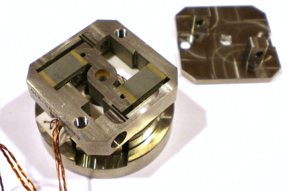
In standing wave motors, an oscillation in the form of a standing wave is generated in a stator by piezoelectric solid state actuators. The resulting, mostly elliptical, movement of one or more contact points drives a rotor. The contact can be temporarily interrupted at high vibration amplitudes, resulting in shocks. Standing wave motors can have many different shapes and generate both rotational and linear movements. The picture on the left shows a rotary standing wave motor driven by four piezo actuators.
Inertia motors
Inertia motors use the inertia of the object to be moved to move it over a frictional contact. In classical inertial motors, a phase of slow motion in frictional contact is subject to static friction, in a phase of rapid motion the inertial forces become so great that the parts slide on top of each other. This change between static friction and sliding friction has led to the widespread designation “stick-slip motors” (from “stick to stick” and “to slip” = sliding) (see stick-slip effect ). But there are also inertial motors that work without detention phases. In these engines, the parts slide on each other during the drive phases.
Piezoelectric inertia motors can be very simple. In the simplest case, they consist of only three components, as in the example opposite. The numerous forms of inertial motors can be distinguished, among other things, according to whether the motor driving solid-state actuator is fixed or moves with the engine. Most inertial motors operate at low frequencies up to a few kHz. However, some resonant inertial motors also work in the ultrasonic range. Inertia motors are z. B. used for sample positioning in microscopy and image stabilization in digital cameras.
Inchworm motors
So-called “inchworm” motors work according to the principle “clamping and sliding” shown opposite. The caterpillar-like movement principle was (. For caterpillar English), which generally describes this type of engine today its name to the brand name “Inchworm”. The motor shown in the picture on the right consists of two clamping actuators and one feed actuator (top and bottom). Because of clocked operation, “inchworm” motors operate at low frequencies in the audible range. They are designed for great power and precision, less for high speed.
Walking motors
Unlike in “inchworm” motors, in so-called stepper motors, the clamping and the drive are taken over by the same and not by different actuators. In the example shown in the adjacent picture, two bending actuators in bimorph design (two actuators plus intermediate layer) are used for this purpose. The contact points at their tips would perform an elliptical motion with free movement. In fact, they press on a part of this track against the “rotor”, the element to be driven, and push it in the desired direction. Due to the phase-shifted movement of the actuators always at least one clamps the rotor, so that it never runs free.
Current designs
One drive technique uses piezoelectric ceramics to push a stator. These piezoelectric motors use three groups of crystals—two locking, and one motive that permanently connects to either the motor’s casing or stator (not both). The motive group, sandwiched between the other two, provides the motion. These piezoelectric motors are fundamentally stepping motors, with each step comprising either two or three actions, based on the locking type. These motors are also known as inchworm motors. Another mechanism uses surface acoustic waves (SAW) to generate linear or rotational motion.
A second drive type, the squiggle motor, uses piezoelectric elements bonded orthogonally to a nut. Their ultrasonic vibrations rotate a central lead screw. This is a direct drive mechanism.
Locking mechanisms
The non-powered behaviour of the first type of piezoelectric motor is one of two options: normally locked or normally free. When no power is applied to a normally locked motor, the spindle or carriage (for rotary or linear types, respectively) does not move under external force. A normally free motor’s spindle or carriage does move freely under external force. However, if both locking groups are powered at rest, a normally free motor resists external force without providing any motive force.
A combination of mechanical latches and crystals can do the same thing, but would restrict the maximum stepping rate of the motor. The non-power behaviour of the second type of motor is locked, as the drive screw is locked by the threads on the nut. Thus it holds its position with the power off.
Stepping actions
Regardless of locking type, stepping type piezoelectric motors—linear and rotary—use the same mechanism to create movement:
First, one group of locking crystals is activated to lock one side and unlock other side of the ‘sandwich’ of piezo crystals.
Next, the motive crystal group is triggered and held. The expansion of this group moves the unlocked locking group along the motor path. This is the only stage where the motor moves.
Then the locking group triggered in stage one releases (in normally locking motors, in the other it triggers).
Then the motive group releases, retracting the ‘trailing’ locking group.
Finally, both locking groups return to their default states.
Direct drive actions
The direct drive piezoelectric motor creates movement through continuous ultrasonic vibration. Its control circuit applies a two-channel sinusoidal or square wave to the piezoelectric elements that matches the bending resonant frequency of the threaded tube—typically an ultrasonic frequency of 40 kHz to 200 kHz. This creates orbital motion that drives the screw.
Speed and precision
The growth and forming of piezoelectric crystals is a well-developed industry, yielding very uniform and consistent distortion for a given applied potential difference. This, combined with the minute scale of the distortions, gives the piezoelectric motor the ability to make very fine steps. Manufacturers claim precision to the nanometer scale. High response rate and fast distortion of the crystals also let the steps happen at very high frequencies—upwards of 5 MHz. This provides a maximum linear speed of approximately 800 mm per second, or nearly 2.9 km/h.
A unique capability of piezoelectric motors is their ability to operate in strong magnetic fields. This extends their usefulness to applications that cannot use traditional electromagnetic motors—such as inside nuclear magnetic resonance antennas. The maximum operating temperature is limited by the Curie temperature of the used piezoelectric ceramic and can exceed +250C.
Other designs
Single action
Very simple single-action stepping motors can be made with piezoelectric crystals. For example, with a hard and rigid rotor-spindle coated with a thin layer of a softer material (like a polyurethane rubber), a series of angled piezoelectric transducers can be arranged. (see Fig. 2). When the control circuit triggers one group of transducers, they push the rotor one step. This design cannot make steps as small or precise as more complex designs, but can reach higher speeds and is cheaper to manufacture.
Patents
The first U.S. patent to disclose a vibrationally-driven motor may be “Method and Apparatus for Delivering Vibratory Energy” (U.S. Pat. No. 3,184,842, Maropis, 1965). The Maropis patent describes a “vibratory apparatus wherein longitudinal vibrations in a resonant coupling element are converted to torsional vibrations in a toroid type resonant terminal element.” The first practical piezomotors were designed and produced by V. Lavrinenko in Piezoelectronic Laboratory, starting 1964, Kiev Polytechnic Institute, USSR. Other important patents in the early development of this technology include:
“Electrical motor”, V. Lavrinenko, M. Nekrasov, Patent USSR # 217509, priority May 10, 1965.
“Piezoelectric motor structures” (U.S. Pat. No. 4,019,073, Vishnevsky, et al., 1977)
“Piezoelectrically driven torsional vibration motor” (U.S. Pat. No. 4,210,837, Vasiliev, et al., 1980)
Benefits
One of the most important advantages of these types of engines is that direct drive is possible for any rotational speed. In a constructive respect, the drive is significantly simplified and in some cases the efficiency significantly increases, which “eats” the gearbox. It is this property that allowed the development of ball valve drives with any flow area (Fig. 5) and their mass production.
In terms of speed, piezoelectric motors have no equal. This is due to the fact that their power does not depend on the mass of the rotor, as is the case for electromagnetic motors. For fractions of a millisecond, they gain the necessary speed and can compete even with expensive piezoelectric actuators, for example, for fuel injectors.
The minimum step of piezomotors can be thousandths of an angular second. On their basis, microscopes guides are created operating in the nanometer range. For low-speed household appliances, due to the lack of a gearbox, they are noiseless and do not emit an odor from burnt windings, which they do not have. The inhibition of the rotor in the disconnected state, the plasticity of the form, the ability to integrate integrally into the product are also useful.
Piezoelectric motors can be made entirely from non-magnetic materials. Some of them can work in conditions of high temperatures (up to 300 degrees Celsius), in vacuum, in strong magnetic fields, in conditions of high radiation, when immersed in water or oil.
Application
An ultrasonic engine can be successfully used in those areas of technology where it is necessary to achieve minimum angular and linear displacements. For example, in astronomy, in space research, where precise orientation is required for very small objects (stars); in accelerators of charged particles, where it is necessary to keep the beam in strictly specified geometrical coordinates; in research when studying the crystallographic structure (orientation of the goniometer head ); in robotics, etc.
Based on piezoelectric motors, the following were developed: drives of antennas and surveillance cameras, electric shavers, drives of cutting tools, tape drive mechanisms, tower street clocks, drives of ball valves, low-speed (2 rpm) drives of advertising platforms, electric drills, drives of children’s toys and mobile prostheses, ceiling fans, robots, etc.
Wave piezoelectric motors are also used in lenses for single-lens reflex cameras. Variations of the name of the technology in such lenses from different manufacturers:
Canon – USM, UltraSonic Motor;
Minolta, Sony – SSM, SuperSonic Motor;
Nikon – SWM, Silent Wave Motor;
Olympus – SWD, Supersonic Wave Drive;
Panasonic – XSM, Extra Silent Motor;
Pentax – SDM, Supersonic Drive Motor;
Sigma – HSM, Hyper Sonic Motor;
Tamron – USD, Ultrasonic Silent Drive, PZD, Piezo Drive.
Samsung – SSA, Super Sonic Actuator;
In the machine tool industry, these engines are used for ultra-precise positioning of the cutting tool.
For example, there are special tool holders for turning machines with a microdrive cutter.
Source from Wikipedia