The Tesla turbine is a bladeless centripetal flow turbine patented by Nikola Tesla in 1913. It is referred to as a bladeless turbine. The Tesla turbine is also known as the boundary layer turbine, cohesion-type turbine, and Prandtl layer turbine (after Ludwig Prandtl) because it uses the boundary layer effect and not a fluid impinging upon the blades as in a conventional turbine. Bioengineering researchers have referred to it as a multiple disk centrifugal pump. One of Tesla’s desires for implementation of this turbine was for geothermal power, which was described in Our Future Motive Power.
Description
The guiding idea for developing Tesla turbine is the fact that in order to attain the highest economy, the changes in the velocity and direction of movement of fluid should be as gradual as possible. Therefore the propelling fluid of Tesla turbine moves in natural paths or stream lines of least resistance.
A Tesla turbine consists of a set of smooth disks, with nozzles applying a moving fluid to the edge of the disk. The fluid drags on the disk by means of viscosity and the adhesion of the surface layer of the fluid. As the fluid slows and adds energy to the disks it spirals into the center exhaust. Since the rotor has no projections it is very sturdy.
Tesla wrote, “This turbine is an efficient self-starting prime mover which may be operated as a steam or mixed fluid turbine at will, without changes in construction and is on this account very convenient. Minor departures from the turbine, as may be dictated by the circumstances in each case, will obviously suggest themselves but if it is carried out on these general lines it will be found highly profitable to the owners of the steam plant while permitting the use of their old installation. However, the best economic results in the development of power from steam by the Tesla turbine will be obtained in plants especially adapted for the purpose.”
This turbine can also be applied to condensing plants operating with high vacuum. In such a case, owing to the very great expansion ratio, the exhaust mixture will be at a relatively low temperature and suitable for admission to the condenser.
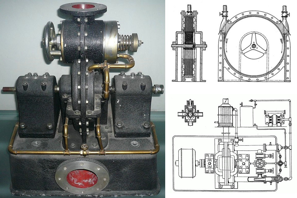
All the plates and washers are fitted on and keyed to a sleeve threaded at the ends and equipped with nuts and collars for drawing the thick end-plates together or the collars may be simply forced onto it and the ends upset. The sleeve has a hole fitting snugly on the shaft, to which it is fastened as usual.
This construction permits free expansion and contraction of each plate individually under the varying influence of heat and centrifugal force and possesses a number of other advantages which are of considerable practical importance. A larger active plate area and consequently more power is obtained for a given width, improving efficiency. Warping is virtually eliminated and smaller side clearances may be used, which results in diminished leakage and friction losses. The rotor is better adapted for dynamic balancing and through rubbing friction resists disturbing influences thereby ensuring quieter running. For this reason and also because the discs are not rigidly joined it is protected against damage which might otherwise be caused by vibration or excessive speed.
The Tesla turbine has the trait of being in an installation normally working with a mixture of steam and products of combustion and in which the exhaust heat is used to provide steam which is supplied to the turbine, providing a valve governing the supply of the steam so that the pressures and temperatures can be adjusted to the optimum working conditions.
As diagrammed, a Tesla turbine installation is:
Able to start with steam alone
A disc type adapted to work with fluids at high temperature.
An efficient Tesla turbine requires close spacing of the disks. For example, a steam-powered type must maintain 0.4 millimeter (.016 inch) inter-disk spacing. The disks must be extremely smooth to minimize surface and shear losses. Disks must also be very thin to prevent drag and turbulence at disk edges. Unfortunately, preventing disks from warping and distorting was a major challenge in Tesla’s time. It is thought that this inability to prevent the disks distorting contributed to the commercial failure of the turbines, because metallurgical technology at the time was not able to produce disks of sufficient quality and rigidity.
Pump
The device can function as a pump if a similar set of disks and a housing with an involute shape (versus circular for the turbine) are used. In this configuration a motor is attached to the shaft. The fluid enters near the center, is given energy by the disks, then exits at the periphery. The Tesla turbine does not use friction in the conventional sense; precisely, it avoids it, and uses adhesion (the Coandă effect) and viscosity instead. It uses the boundary layer effect on the disc blades.
Smooth rotor disks were originally proposed but these gave poor starting torque. Tesla subsequently discovered that smooth rotor disks with small washers bridging the disks in ~12–24 places around the perimeter of a 10″ disk and a second ring of 6–12 washers at a sub-diameter made for a significant improvement in starting torque without compromising efficiency.
Applications
Tesla’s patents state that the device was intended for the use of fluids as motive agents, as distinguished from the application of the same for the propulsion or compression of fluids (though the device can be used for those purposes as well). As of 2016, the Tesla turbine has not seen widespread commercial use since its invention. The Tesla pump, however, has been commercially available since 1982 and is used to pump fluids that are abrasive, viscous, shear sensitive, contain solids, or are otherwise difficult to handle with other pumps. Tesla himself did not procure a large contract for production. The main drawback in his time, as mentioned, was the poor knowledge of materials characteristics and behaviors at high temperatures. The best metallurgy of the day could not prevent the turbine disks from moving and warping unacceptably during operation.
In 2003, Scott O’Hearen took a patent on the Radial turbine blade system. This invention utilizes a combination of the concepts of a smooth runner surface for working fluid frictional contact and that of blades projecting axially from plural transverse runner faces.
Today, many amateur experiments in the field have been conducted using Tesla turbines which use compressed air, steam as its power source (the steam being generated with heat from fuel combustion, from a vehicle’s turbocharger or from solar radiation). The issue of the warping of the discs has been partially solved using new materials such as carbon fiber.
One proposed current application for the device is a waste pump, in factories and mills where normal vane-type turbine pumps typically get blocked.
Tesla turbines are ideal, due to many reasons, for off grid, mini steam turbine, electrical home generation stations, and with some experience, can be fairly easy engineered by hobbyists.
Applications of the Tesla turbine as a multiple-disk centrifugal blood pump have yielded promising results.
Biomedical engineering research on such applications has been continued into the 21st century.
In 2010, U.S. Patent 7,695,242 was issued to Howard Fuller for a wind turbine based on the Tesla design.
Efficiency and calculations
Tesla’s turbine has a very high theoretical yield, about 92%, but in fact there are several constructive constraints that compete to reduce their general performance. To better clarify these constraints, the following is a brief list:
The diameter of the rotor: its sizing must not be separated from the physical characteristics of the fluid that will be used. This constraint means that theoretically it is possible to determine an optimal diameter of the rotor: in fact, a too small rotor can not effectively convert all the kinetic energy present in the injected fluid. On the other hand, a too large rotor can generate an excessive flow for the fluid, with consequent loss of load. Not only that, but a too large disk is difficult to build and, due to the high centrifugal forces it is subjected to, the maximum speed of rotation will be limited.
The space between the surfaces of the discs that make up the rotor: for example, for the steam it is necessary a spacing of about 0.4 mm, it is crucial then that the discs have a minimum thickness, this obviously can be a problem for large discs working at high rotation speeds. In fact the prevention of the possibility of triggering of oscillations in the disks is one of the major problems of this turbine. The difficulty in containing the oscillations is thought to be the main cause of the commercial failure of this invention. However, just in recent years, with the new technologies often derived from the turbojet, it is possible to make thinner and stiff discs with a good surface finish, all elements that can contribute to improve the efficiency of the device.
Surface finish of discs: a rough disc surface can easily generate vortexes that reduce turbine efficiency, so it is important that these are made with smooth and very well finished surfaces.
Positioning and geometry of the input nozzle: being the Tesla turbine a device that exploits the kinetic energy of the fluid introduced into it, the characteristics of the nozzle that brings the fluid to have a high speed and therefore kinetic energy, are determinants, realizing such nozzles without turbulence is particularly critical.
The geometry of the inlet edge of the discs: the velocity of the fluid that touches the edge of the disc can be supersonic and therefore, in this area, compression waves can be created that can generate losses and alterations in the fluid path.
The size and geometry of the exhaust pipes light: even if at the exit of the turbine the fluid velocity is lower, the design of the exhaust is critical, and even in this phase, harmful vorticity can occur with consequent losses; in fact the flow is centripetal, (from the periphery to the center of the disk), and then axial (aligned with the axis of rotation); with rotating discs at high speed, the conveying of a rotating fluid in an axial duct without turbulence is not easy.
In Tesla’s time, the efficiency of conventional turbines was low because turbines used a direct drive system that severely limited the potential speed of a turbine to whatever it was driving. At the time of introduction, modern ship turbines were massive and included dozens, or even hundreds of stages of turbines, yet produced extremely low efficiency due to their low speed. For example, the turbine on the Titanic weighed over 400 tons, ran at just 165rpm, and used steam at a pressure of only 6 PSI. This limited it to harvesting waste steam from the main power plants, a pair of reciprocating steam engines. The Tesla turbine also had the ability to run on higher temperature gasses than bladed turbines of the time contributed to its greater efficiency. Eventually axial turbines were given gearing to allow them to operate at higher speeds, but efficiency of axial turbines remained very low in comparison to the Tesla Turbine.
As time went on, competing Axial turbines became dramatically more efficient and powerful, a second stage of reduction gears was introduced in most cutting edge U.S. naval ships of the 1930s. The improvement in steam technology gave the U.S. Navy aircraft carriers a clear advantage in speed over both Allied and enemy aircraft carriers, and so the proven axial steam turbines became the preferred form of propulsion until the 1973 oil embargo took place. The oil crisis drove the majority of new civilian vessels to turn to diesel engines. Axial steam turbines still had not exceeded 50% efficiency by that time, and so civilian ships chose to utilize diesel engines due to their superior efficiency. By this time, the comparably efficient Tesla turbine was over 60 years old.
Tesla’s design attempted to sidestep the key drawbacks of the bladed axial turbines, and even the lowest estimates for efficiency still dramatically outperformed the efficiency of axial steam turbines of the day. However, in testing against more modern engines, the Tesla Turbine had expansion efficiencies far below contemporary steam turbines and far below contemporary reciprocating steam engines. It does suffer from other problems such as shear losses and flow restrictions, but this is partially offset by the relatively massive reduction in weight and volume. Some of Tesla turbine’s advantages lie in relatively low flow rate applications or when small applications are called for. The disks need to be as thin as possible at the edges in order not to introduce turbulence as the fluid leaves the disks. This translates to needing to increase the number of disks as the flow rate increases. Maximum efficiency comes in this system when the inter-disk spacing approximates the thickness of the boundary layer, and since boundary layer thickness is dependent on viscosity and pressure, the claim that a single design can be used efficiently for a variety of fuels and fluids is incorrect. A Tesla turbine differs from a conventional turbine only in the mechanism used for transferring energy to the shaft. Various analyses demonstrate the flow rate between the disks must be kept relatively low to maintain efficiency. Reportedly, the efficiency of the Tesla turbine drops with increased load. Under light load, the spiral taken by the fluid moving from the intake to the exhaust is a tight spiral, undergoing many rotations. Under load, the number of rotations drops and the spiral becomes progressively shorter. This will increase the shear losses and also reduce the efficiency because the gas is in contact with the discs for less distance.
Efficiency is a function of power output. A moderate load makes for high efficiency. Too heavy a load increases the slip in the turbine and lowers the efficiency; with too light a load, little power is delivered to the output, which also decreases efficiency (to zero at idle). This behaviour is not exclusive to Tesla turbines.
The turbine efficiency of the gas Tesla turbine is estimated to be above 60, reaching a maximum of 95 percent. Keep in mind that turbine efficiency is different from the cycle efficiency of the engine using the turbine. Axial turbines which operate today in steam plants or jet engines have efficiencies of about 60–70% (Siemens Turbines Data). This is different from the cycle efficiencies of the plant or engine which are between approximately 25% and 42%, and are limited by any irreversibilities to be below the Carnot cycle efficiency. Tesla claimed that a steam version of his device would achieve around 95 percent efficiency. Actual tests of a Tesla steam turbine at the Westinghouse works showed a steam rate of 38 pounds per horsepower-hour, corresponding to a turbine efficiency in the range of 20%, while contemporary steam turbines could often achieve turbine efficiencies of well over 50%. The thermodynamic efficiency is a measure of how well it performs compared to an isentropic case. It is the ratio of the ideal to the actual work input/output. Turbine efficiency is defined as the ratio of the ideal change in enthalpy to the real enthalpy for the same change in pressure.
In the 1950s, Warren Rice attempted to re-create Tesla’s experiments, but he did not perform these early tests on a pump built strictly in line with the Tesla’s patented design (it, among other things, was not a Tesla multiple staged turbine nor did it possess Tesla’s nozzle). Rice’s experimental single stage system’s working fluid was air. Rice’s test turbines, as published in early reports, produced an overall measured efficiency of 36–41% for a single stage. Higher percentages would be expected if designed as originally proposed by Tesla.
In his final work with the Tesla turbine and published just prior to his retirement, Rice conducted a bulk-parameter analysis of model laminar flow in multiple disk turbines. A very high claim for rotor efficiency (as opposed to overall device efficiency) for this design was published in 1991 titled “Tesla Turbomachinery”. This paper states:
With proper use of the analytical results, the rotor efficiency using laminar flow can be very high, even above 95%. However, in order to attain high rotor efficiency, the flowrate number must be made small which means high rotor efficiency is achieved at the expense of using a large number of disks and hence a physically larger rotor. For each value of flow rate number there is an optimum value of Reynolds number for maximum efficiency. With common fluids, the required disk spacing is dismally small causing [rotors using] laminar flow to tend to be large and heavy for a prescribed throughflow rate.
Extensive investigations have been made of Tesla-type liquid pumps using laminar-flow rotors. It was found that overall pump efficiency was low even when rotor efficiency was high because of the losses occurring at the rotor entrance and exit earlier mentioned.
Modern multiple stage bladed turbines typically reach 60–70% efficiency, while large steam turbines often show turbine efficiency of over 90% in practice. Volute rotor matched Tesla-type machines of reasonable size with common fluids (steam, gas, and water) would also be expected to show efficiencies in the vicinity of 60–70% and possibly higher.
Influences
Tesla turbine model makers can easily build turbine models using optical discs (CDs or compact discs ) to compose the wheel, obviously with interposed spacers and an appropriate central hole, polymethylmethacrylate (Plexiglas) or a whole series of analogs, for the case and the nozzle, which among other things have the advantage of being transparent, and compressed air at high pressure as a motor fluid.
Source from Wikipedia